Abrasion Testing
Accelerated Life Testing
Chemistry Laboratory
Computer Modeling
Salt Spray Testing
Density
Electrical Properties
Electron Microscopy
Experimental Foundry
Failure Analysis
Hardness Laboratory
Heat Treatment Studies
Light Microscopy
Lubrication Testing
Machine Shop
Materials Databases
Mechanical Testing
Metallography
Paint & Coatings
Product Testing
Rolling Mill
Thermal Testing
Conductivity Testing – Electrical Properties Testing
The resistivities of bars, rods, or other constant cross-section samples of larger dimension can be determined by this method, with one modification.

Electrical Conductivity of Solids
For conductivity testing, the standard test method for determining the resistivity of electrical conductor materials is ASTM B 193-87. Conductivity is calculated from the measured resistance and dimensions of the specimen. The accuracy and convenience with which resistance can be measured depends on the actual resistance of the specimen. A long, thin specimen may be required if the specimen is a very good electrical conductor. Electrical conductivity of aluminum alloys varies with its composition and microstructural state. The conductivity of aluminum alloys is used to correlate to the extent of solutes retained in solid solution. In metal matrix composites, conductivity is a function of the microstructural state of the matrix alloy and is inversely proportional to the volume of fibers.
Electrical resistance can be measured directly using an Ohmmeter when the resistance of the specimen is more than one ohm and contact resistance to the specimen is negligible. A bridge circuit or potentiometer must be used when the electrical resistance can not be measured directly.
Conductance is the reciprocal of the resistance. Conductivity is likewise the reciprocal of the electrical resistivity. Our current set-up allows resistance measurements between 30 m? and 30 M?.
Four-Point Probe Method for Conductive Solid Samples
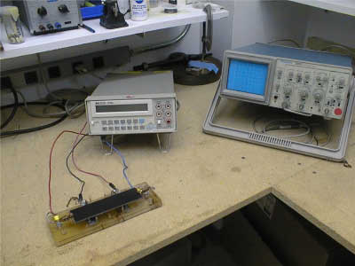
The electrical resistivity of conductive fibers and small diameter wires can be determined by a four-point probe method. Four copper wires are stretched across the opening of a teflon (or other non-conductive plastic block), glued in place, parallel, and with precisely-known separation (gage length) between the two inner wires. All four wires then are connected to individual copper terminal blocks. The two outer leads are connected to a precision current source and the two inner leads are used to measure voltage drop. The sample fiber or wire is laid across the lead wires and may be pasted in place using conductive silver paint. Ohm’s law (V = IR) allows the resistance (R) to be determined. Coupled with cross-sectional area (A) measurement of the sample and the known gage length (L), the resistivity is = RA/L.
Four-Point Probe Method for Conductive Fibers
The resistivities of bars, rods, or other constant cross-section samples of larger dimension can be determined by this method, with one modification. To ensure that a constant potential is applied across the entire cross-section of the sample, copper plates are affixed to the sample at its ends by silver paste. To these plates is applied the test voltage. The current is again measured using fine wire leads or knife-edge supports of precise separation.

